DAF Systems > Dissolved Air Flotation (DAF) Systems (V Series)
Dissolved Air Flotation (DAF) is a water treatment process that clarifies wastewater through the removal of suspended matter such as oil, greases or solids. Removal is achieved by injecting pressurized air into the wastewater where micro-bubbles then interact with the suspended solid particles. This interaction causes these particles to float to the surface of the DAF where they are then skimmed and separated.
- Performance guarantee providing assurance that your discharge requirements will be met or exceeded.
- Cleanest effluent levels of any Dissolved Air Flotation (DAF) presently available with TSS as low as 5 ppm.
- Lowest ongoing maintenance requirements of any Dissolved Air Flotation (DAF) system.
- Compact, optimized foot print that is also easy to operate and maintain.
- Capable of producing 10% dry sludge.
- Increased air to solid ratio.
- Air bubbles down to 5 microns in size (allowing for greater sludge separation and dryer sludge).
- Multi-Point Air Injection creating a constant upward pressure on the sludge.
- Counter Flow Sludge Skimming eliminating possibility of driving sludge back into the cleaner water.
- Weir and skimmer system polisher at the final stage of the process, resulting in lowering TSS count in effluent water.
Ecologix High Performance 99.9% TSS/FOG & 75% BOD Reduction - Dissolved Air Flotation System
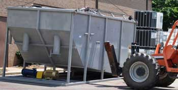
- 304 Stainless Steel construction.
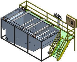
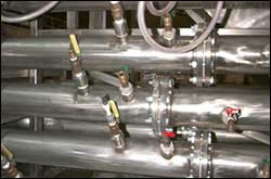
- Overall customized to fit allocated space - Includes stainless header entering DAF including four ½” penetrations with ½” ball valves for whitewater addition/chemical addition/sample port.
- Recirculation aeration pump with aeration valves.
- Surface skimmer system complete with #50 SS chain and four (4) SS skimmer blades - Bolt-on and manually adjustable. VFD motor 0-13rpm, 195:1 gear reduction.
- Bottom settled solids removal cones with dump valves Effluent weirs with Quick-Release Locking Handles (manually adjustable)
- One (1) 2” air driven sludge transfer pump Staircase and Catwalk for DAF – Bolt work platform and staircase frame made of carbon steel with safety yellow fiberglass grating.
- Chemical Metering Feed Pumps (pH, Coagulation, Flocculation) Control System, featuring:
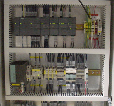
- NEMA 4X stainless steel enclosure with fused disconnect(s).
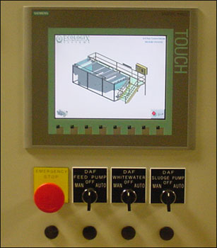
- Allen Bradley PLC Control System with touch screen - including aeration and chemical feed pumps
- All necessary starters, fuse disconnects, status lights, switches.
- Common 460V/3/60 power supply required.
- Common 460V/3/60 power supply to be provided by customer.
| General Description | |
| DAF is a highly efficient method for removal of turbidity, color, suspended solids and other contaminants from water. A recirculation loop of pressurized water is saturated with dissolved air using a multistage impeller pump. The product of this process is termed “whitewater.” Whitewater discharges into calculated points along the pipe flocculator. Microscopic air bubbles become entrained in the floc particles. When the floc particles leave the pipe flocculator and enter the body of the DAF, they rise to the surface and form a sludge blanket. As the sludge blanket thickens, a skimmer drive transfers sludge to the DAF sludge sump. From the sump, sludge is pumped to dewatering equipment. The treated water gravity flows from the DAF vessel to a clear well or city discharge point. | |
| Flocculation Mixing Tube | |
 |
|
| Pressurized Water Recirculation | |
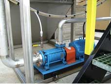
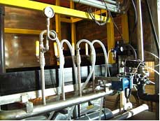
Clean, treated water removed from the wastewater discharge cell is pressurized and fed back into the system via inlet ports on the flocculator. Additionally, pressurized water is injected into the flotation cell. The Pressurized Recirculation Loop Creates Whitewater, which is a key factor to water treatment success. The Pressurization Pump is sized to provide adequate recirculation water flow at 400’ TDH. The pump is installed on the DAF flotation cell skid. The Air Dissolving Tank provides the retention time necessary to allow injected air to dissolve, creating “whitewater”. The tank is supplied complete with internal piping, inlet/outlet flanges, pressure gauge, pressure bleed-off valve, and air control assembly (solenoid valve, filter/ regulator/gauge, rotometer, and check valve).
  |
|
| Dual Chamber Chemical Reaction Tank | |
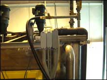
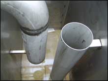
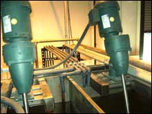
The Reaction tank is designed specifically as an option to allow for longer chemical contact time. The tank allows for 5 minutes of chemical reaction time per chamber. The Dual Chamber Reaction Tank features plate mounted agitators and typically utilizes a Walchem dual probe pH controller to aid in automated chemical dosage and operator monitoring. The unit can also be outfitted with a stainless steel chemical metering pump stand for application of sulfuric acid, acidic coagulants or caustic soda. This feature allows for short distance pipe runs of hazardous chemicals and minimizes operator exposure.
   |
|
| Flotation Cell | |
| The flotation cell is a rectangular vessel designed to provide controlled influent wastewater velocity and optimized surface area. It contains an inlet diffusion pipe, sludge rake, and one or more blow-down valves. The blow-down valve permits removal of the small portion of sludge that settles in the flotation cell. | |
| Sludge Rake | |
The sludge rake assembly consists of a stainless steel chain and a three-blade scraper arrangement. The sludge scrapers skim the surface of the sludge in the flotation cell and transfer the floating solids to the sludge sump. From the sludge sump a pump removes the sludge to the Thickening/Sludge Dewatering Tank.
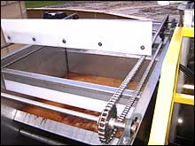 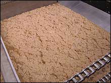 The Sludge Rake moves the Floating Sludge Blanket to the Sludge Sump for removal. The Sludge Rake Operates with Variable Speed Control on an Adjustable Timer that is Set According to Flow Rate and Solids Loading. |
|
| Sludge Sump | |
| Thickened sludge skimmed from the DAF discharges into a sludge sump. The sump has a hopper bottom with inclined sides to allow sludge to gravity feed to the suction side of the sludge transfer pump. | |
| Discharge Cell | |
| The discharge cell is designed to allow clean, treated water to flow downward and away from rising sludge, and then upward through a clear-well section. It contains a wastewater baffle, adjustable weir, pressurized water diffusion pipe, and blow-down valve. Clean, treated effluent, flows down and under the flotation cell, upward through a clear-well and then over an adjustable weir into a collection launder. The weir is made to be adjustable with threaded bolts. A portion of the clean, treated water, is removed from this cell via a recirculation water header piped to the suction inlet of the pressurized water recirculation pump. A portion of the pressurized water is piped into the inclined section of the flotation cell. A blow-down valve permits removal of the small portion of sludge that settles in the discharge cell. As a result of these extra clarification steps our clean water is commonly as much as 5-6 times purer than other competitive DAF systems. | |
| Clear Well & Dewatering | |
| Some systems employ a clear well for finished clean water inspection, post pH adjustment, or as a short term holding reservoir when the water needs to be transferred to another location for discharge or reuse. The clear well is constructed as a low side wall stainless steel tank for easy visual reference of effluent quality. | |
| Mechanical Construction | |
| The DAF vessel is constructed of 304L Stainless Steel with suitable stiffeners to prevent deformation under all normal stresses incurred during erection and operation. The unit can also be skid-mounted for mobility. All joints are double welded and leak tested prior to shipment. A DAF-mounted catwalk and ladder are provided for operator access to the top of the DAF vessel on large units. Handrails are painted yellow per OSHA regulations. The DAF mixing-pipe flocculator is fabricated out of 304L Stainless Steel (316SS is optional). The flocculator is mounted on legs, and connects to the main DAF unit via a 150lb flange. The flocculator and DAF system are pressure tested prior to shipment. | |
| Automatic Control Systems | |
| The control panel for each system can be designed to include as much or as little automation as desired by the operator and project engineers. They are designed to provide fully automatic operation utilizing a PLC (Programmable Logic Controller). User interface with the control system is provided in the form of panel-mounted selector switches, Allen-Bradley AC variable drive terminals, a pH controller, alarm with lights/horn and a panel-mounted process display terminal. Process variables and chemical dosage set points are monitored and changed via the panel-mounted display terminal. Chemical pump rates follow process flow which is monitored and controlled by a magmeter and proportional valve. Polymer usage is automatically displayed in ml/min and lbs/day on the panel-mounted display. System kilowatt-hour usage is also monitored and displayed. A fail-safe operation mode is provided that will allow the system to be operated manually in the event of a computer malfunction. A semi-automatic mode is also designed into the Ecologix control system to provide maintenance and operational flexibility. | |
| Sludge Holding Tank / Dewatering | |
| The sludge that has been removed from the wastewater by the scraper is pumped into a sludge holding tank for further thickening. From there it is pumped into a dewatering system such as Filter Press or Belt Press for final dewatering. The end result is a 25%-50% dry sludge by weight that is solid to the touch and can be safely disposed of to a land fill. |
Most common industries served by Ecologix DAF Systems |
||||||||
Food Processing:
|
Heavy Industry:
|
Other:
|
||||||
METALS REMOVALRemoves all common metals to less than 1ppm and into the parts per billion (ppb) level count in a continuous flow process at flow rates up to and over 1,000 GPM. Oils, grease and other contaminants are removed in the same step. Because the CRM operates in a continuous process, you can run the rest of your plant without worrying about overloading the waste treatment system.
POULTRY PROCESSINGThe V series DAF system for the Poultry Processing Industry treats every type of waste stream created by eviscerating, further processing and cleaning. The system operates in a continuous process using minimal amounts of chemistry in a self-contained, skid-mounted unit that uses little floor space and requires minimal operator intervention. The powerful microscopic bubbles float solids to the surface as shown to the right.
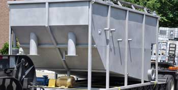
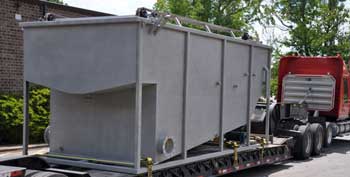
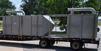
The Application Ecologix supplies wastewater treatment systems to both poultry kill plants and further processing plants. Poultry processing creates different types of waste streams depending on the type of plant and its products. Kill Plants First Shift (slaughter) Second Shift (cleaning) Further Processing The Challenge INDUSTRIAL LAUNDRY and TEXTILE RENTALOur DAF systems apply to both Industrial Laundry operations and Textile Rental companies operating their own washing plants.The Application Challenges Depending on the product mix in the washroom, the time of day, the season or other factors, the nature of the waste stream sent to the waste treatment system can fluctuate widely. Traditional waste treatment methods rely on large equalization tanks and long dwell times to archive proper treatment conditions. These systems use large quantities of chemicals and take up vast amounts of valuable floor space. On top of the waste treatment challenges, water supplies are dwindling and the cost of clean incoming plant water is becoming significant. DAF SHIPPING PHOTOS
DAF CONTROL PANEL PHOTOS
|
||||||||


