326-2020/(678)514-2100")
Bio-Clear Treatment Systems > Bio-Clear (DSA) Deep Shaft Aeration
The Bio-Clear (DSA) effluent treatment system is a state-of-the-art high-rate aerobic activated sludge process that provides a compact, robust, and low maintenance wastewater solution. The systems core difference to traditional treatment plants is its use of deep shaft technology that has been widely used for more than 25 years. The innovative use of this methodology dramatically reduces capital and operating costs while providing substantial performance improvements.Process Summary
typically 150-300 ft deep. and can be treated separately if necessary. |
 |
Bio-Clear (DSA) Key Features
|
The following key features give Bio-Clear (DSA) a strong advantage over all other competing biological treatment processes, including sequential batch reactors (SBRs), conventional activated sludge processes and aeration ponds:
|
  |
Applications
The Bio-Clear (DSA) process is ideal for treating biodegradable industrial wastewater streams and municipal sewage. It has particular advantages in applications with the following conditions that can make conventional processes unsuitable:- Sites with space constraints
- Wastewater streams with high VOC content
- Retrofits and plant expansions
- Applications with very concentrated wastewater streams
- Sites with high precipitation or extreme temperatures
- Sites close to residential developments
- Applications with fluctuating loads
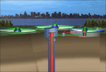
- Locations where large unsightly plants are undesirable such as recreation areas
- Sites in areas with high seismic activity
- Wastewater streams prone to foaming
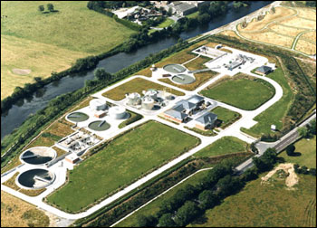
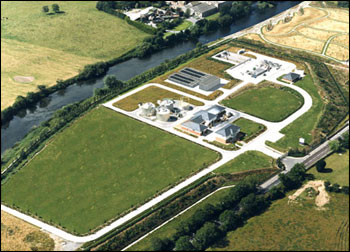
Comparison of municipal Wastewater Treatment Systems
 |
 |
Traditional Wastewater Treatment Plant Footprint |
Wastewater Treatment Plant Footprint using Bio-Clear (DSA) |
Core Reactor Features
The principal difference between Bio-Clear (DSA) and other technologies employing in-ground hyperbaric aeration reactors is that the Bio-Clear (DSA) reactor has been reconfigured to incorporate three separate treatment zones, giving it a significant capital and operating cost advantage over similar old-generation technologies.
The oxidation zone is the upper portion of the reactor and includes a central concentric draft tube for mixed liquor circulation.
The mixing zone is immediately below the oxidation zone. Air, as required for high rate bio-oxidation within the upper zone of the reactor is injected into the mixing zone. The injected air also provides the drive mechanism for airlift circulation.
The saturation zone, or oxygen soak zone, occupies the bottom of the reactor. Installed by conventional drilling or excavation techniques, the Bio-Clear (DSA) reactor is typically 75 m to 110 m (250 ft to 350 ft) deep, occupying only a fraction of the area used by conventional surface basins and using only about 10% of the air consumed by conventional aeration systems. The diameter of the reactor, nominally 0.75 m to 6 m (2.5 ft to 20 ft), is determined by the quantity and strength of the material to be treated.
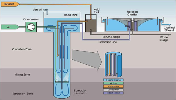
Process Description
Hold TankThe screened and degritted influent stream flows from outside of the Battery Limit to the hold tank, where it is mixed with return activated sludge. No primary clarifiers are required.
Aerated Shaft (Bioreactor) and Head Tank
Air is injected into the mixing zone and the rising bubbles travel up the annulus creating a density gradient resulting in airlift circulation within the oxidation zone. Influent is drawn through the action of the airlift effect from the hold tank into the bioreactor, where it remains in contact with the air and biomass for several minutes before it reaches the head tank.
The bioreactor operates at a high hydraulic pressure and can obtain, as a result, an oxygen transfer efficiency of over 65%. This high oxygen transfer rate minimizes the air requirement, off-gas flow, potential for foam generation, and results in more than a 50% saving in aeration power cost. High reaction rates within the oxidation zone ensure that the bulk of the organic compounds are bio-oxidized in this updraft portion of the vertical circulating loop.
Recirculating liquor travels up the riser and enters the head tank where entrained spent off-gas bubbles are allowed to escape to the atmosphere. Removal of the gaseous products of microbial respiration is necessary to prevent spent gas from re-entering the system and impairing the efficiency of the airlift mechanism. This vent stream can be conveniently treated in a biofilter to remove VOCs if required. The high oxygen content in the mixed liquor minimizes the potential for nuisance odor from the facility.
A proportionately smaller fraction of the mixed liquor moves from the mixing zone through the lower polishing zone (or saturation zone) within the reactor. This zone is characterized by high dissolved oxygen concentration and a relatively longer residence time resulting in a high degree of residual BOD oxidation. The high dissolved gas concentration in the polishing zone also drives solids separation in the flotation clarifier.
Air Compressor
Air is supplied by rotary screw compressors, including an installed spare, at a flow rate based on the dissolved oxygen content in the head tank. The air that is introduced to the bioreactor aids in several process functions. Not only does the air satisfy the primary requirement of providing the microbes with dissolved oxygen, it also serves as an airlift pump, thus eliminating the need for mixers in the bioreactor. The air also provides the dissolved gases necessary for solids flotation in the flotation clarifier that follows the bioreactor, thereby minimizing the size of the downstream separation equipment.
Dissolved Air Flotation Clarifier (DAF)
The effluent from the bioreactor flows by gravity to dissolved air flotation clarifiers, which remove solids from the treated effluent. This transfer occurs rapidly to ensure that grit or solids do not settle out in the bottom of the reactor. Each clarifier is hydraulically designed to permit maintenance shutdowns of a clarifier without disrupting plant operation.
When, the supersaturated mixed liquor is brought to the clarifier from the bottom of the bioreactor, the rapid depressurization results in an extremely well-aerated, low-density floc and immediate separation of the biomass from the effluent. The biomass thickens to approximately 4% solids on the surface of the clarifiers. High quality treated effluent from the clarifiers is ready for disinfection (in municipal applications) and subsequent discharge.
A portion of the sludge is recycled to the holding tank by gravity, and waste sludge pumps, one of which is an installed spare, pump excess solids to the Battery Limit. No down-stream thickener is required.
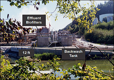
Effluent Biofilters
In some applications, the clarified effluent flows by gravity to nitrification biofilters, served by centrifugal air blowers, one of which is an installed spare. Filtered effluent flows by gravity to a backwash tank, where it is either routed to the filter as backwash water, or is discharged to the Battery Limit. The biofilters are periodically backwashed with treated effluent using an intermittent backwash pump. Spent backwash water is recycled to the hold tank. The intermittent backwash can be a manual filter washing sequence, or if desired, can be fully automated and controlled by the PLC system.
The nitrification biofilters are down-flow, fixed film biofilters containing acclimatized biomass on porous media. These biofilters polish any remaining organic material (refractory material) that takes longer to biodegrade, removing residual TSS and BOD to very low levels and nitrifying the effluent.
Performance
Effluent Characteristics
The Bio-Clear (DSA) reactor will reliably achieve over 95% BOD reduction in a single stage. An average effluent quality of 10 mg/L BOD and 10 mg/L TSS is easily achievable in most municipal applications with a single reactor stage. Concentrated industrial wastewater can typically be treated to a similar specification in two stages. The effluent quality can be improved further by including effluent biofilters, which can be designed for additional BOD and solids removal, nitrification, and/or denitrification, depending on the specific requirements.
Expected Sludge Characteristics
Experience with municipal sewage indicates that the biomass production is less than 0.5 kg per kg of incoming BOD. The total equivalent primary and secondary sludge production is typically less than 1.2 kg of solids per kg of incoming BOD at an average of approximately 3% to 4% total solids, without polymer addition. Sludge production from industrial wastewater is application specific, but the solids concentration is still typically 3% to 4% total solids without polymer addition.
Gaseous Emissions
Gaseous emissions from the Bio-Clear (DSA) system are considerably less than those from conventional aeration processes. Head tank off-gas can be vented or conveniently collected and piped to a biofilter for nearly complete destruction of VOCs. Gas emissions from the flotation clarifiers amount to less than 5% of those from the head tanks and are not collected.
Utility and Chemical Requirements
Electric Power
The typical aeration power requirement is less than 0.8 kW·h/kg (0.5 hp·h/lb) of BOD treated. Most conventional aeration processes have considerably higher power requirements.
Polymer
Polymer consumption can be eliminated by steady operation within the design limits and is not typically required. This gives a considerable cost saving over conventional processes, most of which require continuous polymer feed.
Bio-Clear (DSA) systems are designed to meet effluent specification without polymer addition during peak flows that are with the design limits. If desired, a polymer feed system can be included to allow addition of polymer for control of solids separation during periods of high load or upset conditions. Approximately 5 mg/L of cationic polymer will help maintain effluent specification during periods when the influent loading is outside the design specifications.
Process Water
Process water will be used for general plant wash-down and polymer make-up if polymer is used.