326-2020/(678)514-2100")

Oil Water Separators > Hopper Separator
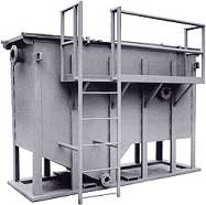
Oil water separators are systems used as an efficient method to separate oils and some solids from a variety of wastewater discharges. They are typically installed in industrial and maintenance areas and receive oily wastewater. The effluent from oil/water separators is typically discharged to either a sanitary sewer system or a storm sewer. Properly designed, installed, and operated, oil/water separators provide a treatment system for handling oily wastewater that prevents the entry of unacceptable levels of contamination to a storm sewer or sanitary sewer system.HQB Features & Benefits
|
Features & Benefits |
|
||||||||||||||||||||||||||||||||||||||||||||
| Operation The separator shall be a special purpose prefabricated parallel corrugated plate gravity displacement type oil/water separator designed to remove free and dispersed non-emulsified oil and settlable solids, in accordance with API 421. The separator shall be comprised of a tank containing: Inlet Compartment The inlet chamber will be comprised of a non-clog diffuser pipe to distribute the flow across the width of the separator chamber. The inlet compartment shall be of sufficient volume to effectively reduce influent suspended solids, dissipate energy and begin separation. A sludge hopper will be provided to prevent settlable solids and sediment from entering the separation chamber. Separation Chamber The separation chamber will contain parallel corrugated plates for enhanced oil/water separation. The plates will be spaced for optimum removal of free oil and settleable solids, and the corrugations will have a 45 to 60 degree angle with respect to the horizontal. Flow through the plate pack will be in a cross-flow configuration. This allows the oil to collect and coalesce in the high points of the corrugations while the solids collect at the low points. This also allows oil to rise without interfering with the falling solids, reducing the possibility of clogging. Plates shall be enclosed in a stainless steel frame to facilitate installation and removal. Sludge Hopper The sludge hopper will be located prior to the separation chamber and will provide an adequate volume and baffling for the settling of any solids. Oil Collection The oil will be collected at the end of the separation chamber by a fixed weir trough or rotatable skimmer. Either collection method will provide automatic decant of the separated oil through gravity outlet(s) on the side(s) of the separator. The type of oil collector depends upon the application. Integral Oil Storage Compartment An integral oil storage compartment can be provided for storing separated oil. The compartment adjacent to the coalescing compartment would collect and store the oil discharged from the oil collector. Clean Water Chamber The water will pass under the oil retention baffle and over the adjustable effluent weir, which maintains the liquid level throughout the separator, and exit through the outlet provided at the end of the separator. The separator is provided with a vapor tight cover that can easily be removed for service and maintenance.
|
||||||||||||||||||||||||||||||||||||||||||||||
| Single Hopper | ||||||||||||||
| Model | Inlet/Outlet | Met Thk. | Width (in.) | Height (in.) | Length (in.) |
Inlet Height | Outlet Height | Anchor Dim. | Anchor Dim. | H Oil Outlet Height | Oil Res. (Gal.) | Sludge Capacity | Ship. Wgt. (Lbs.) | Oper. Wgt. (Lbs.) |
| HP-1 | 3" |
0.18 |
32 |
104 |
74 |
60 |
56 |
16 |
116 |
42 |
25 |
80 |
2870 |
8250 |
| HP-2 | 3" |
0.18 |
32 |
116 |
86 |
60 |
56 |
16 |
116 |
42 |
45 |
80 |
3250 |
8650 |
| HP-3 | 6" |
0.25 |
44 |
116 |
86 |
60 |
56 |
28 |
116 |
42 |
60 |
115 |
3910 |
12000 |
| HP-4 | 6" |
0.25 |
56 |
116 |
86 |
60 |
56 |
40 |
116 |
42 |
75 |
155 |
4570 |
15500 |
| HP-5 | 8" |
0.25 |
68 |
116 |
86 |
60 |
56 |
52 |
116 |
42 |
90 |
195 |
5200 |
18700 |
| HP-6 | 8" |
0.25 |
80 |
116 |
86 |
60 |
56 |
64 |
116 |
42 |
105 |
230 |
5900 |
22000 |
| HP-7 | 10" |
0.25 |
92 |
116 |
86 |
60 |
56 |
76 |
116 |
42 |
120 |
270 |
6600 |
25300 |
| HP-8 | 10" |
0.25 |
104 |
116 |
86 |
60 |
56 |
88 |
116 |
42 |
135 |
310 |
7200 |
28600 |
Double Hopper |
||||||||||||||
| Model | Inlet/Outlet | Met Thk. | Width (in.) | Height (in.) | Length (in.) |
Inlet Height | Outlet Height | Anchor Dim. | Anchor Dim. | H Oil Outlet Height | Oil Res. (Gal.) | Sludge Capacity | Ship. Wgt. (Lbs.) | Oper. Wgt. (Lbs.) |
| DHP-7 | 8" |
0.25 |
92 |
98 |
176 |
72 |
68 |
76 |
156 |
42 |
175 |
400 |
8,700 |
38,000 |
| DHP-8 | 8" |
0.25 |
104 |
98 |
176 |
72 |
68 |
88 |
156 |
42 |
225 |
480 |
9,700 |
43,200 |
| DHP-9 | 10" |
0.25 |
116 |
98 |
176 |
72 |
68 |
100 |
156 |
42 |
275 |
560 |
10,700 |
48,400 |
| DHP-10 | 10" |
0.25 |
128 |
98 |
200 |
84 |
80 |
112 |
180 |
42 |
325 |
640 |
11,700 |
53,600 |
| DHP-1H | 12" |
0.25 |
128 |
110 |
200 |
84 |
80 |
112 |
180 |
42 |
325 |
640 |
13,100 |
70,600 |
| DHP-2H | 12" |
0.25 |
128 |
122 |
200 |
84 |
80 |
112 |
180 |
42 |
325 |
640 |
14,500 |
81,500 |