326-2020/(678)514-2100")

Oil Water Separators > Above Ground Oil Water Separators (ECOS)
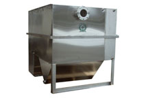
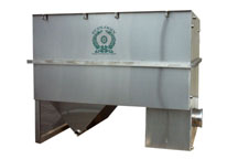
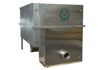
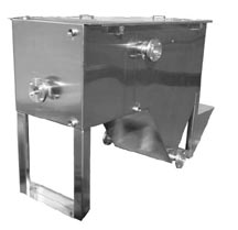
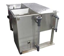
Oil water separators are systems used as an efficient method to separate oils and some solids from a variety of wastewater discharges. They are typically installed in industrial and maintenance areas and receive oily wastewater. Our line of above ground oil water separators will assist in the removal of large quantities of free oil from your wastewater before any further treatment step you may have in your process. We have above ground oil water separators with flow rates ranging from 2 to 70 gallons per minute and capacities up to over 1000 gallons.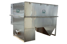 |
 |
 |
 |
Features & Benefits
|
|
Design
The Ecologix Oil Separators (ECOS) are designed
to exceed your expectations. We start off by collecting
the best possible information concerning the wastewater
influent characteristics, operation and maintenance
of the equipment, and the effluent requirements
to be met. We take into consideration the flow
rate (pumped or gravity), fluid temperature range,
density and viscosity, oil droplet size and distribution,
and the specified discharge requirements. Our
design meets or exceeds the guidelines of API-421
and ASTM-D19.31.11.4.
Ecologix oil/water separators use parallel corrugated
plate technology that causes oil droplets to increase
in size, thereby speeding the gravity separation
process according to Stokes’ Law. We offer
a unique inclined plate design design, called
HD Q-PAC,
with an internal structure of interconnecting
plates having many crossing points between adjacent
plates; as the oil water mixture flows through
the separator, new droplets coalesce with retained
droplets to form larger droplets. The enlarged
droplets are released, and they rise to the surface
where they decant from the separator. Since the
Stokes’ Law calculations presume a zero
velocity flow through the HD Q-PAC Plates, a Reynold’s Number less
than 500 will ensure optimum separation in the
oil water separator.Ecologix offers Oil/Water
Separators for separation treatment of groundwater
from free phase LNAPL and DNAPL contaminants.
Operation
Specifications
Fabrication
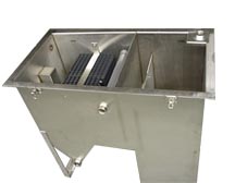
The oil water separator is a special purpose prefabricated
parallel corrugated plate, rectangular, gravity
displacement, type oil water separator. The separator
shall be comprised of a tank containing an inlet
compartment, separation chamber, sludge chamber,
and clean water outlet chamber.
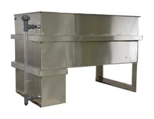
Tank
The tank shall be a single wall construction conforming
to ASTM A240, type 304 stainless steel. Welding
will be in accordance with AWS D1.1 to provide
a watertight tank that will not warp or deform
under load. Pipe connections to the exterior shall
be as follows:
Pipe Connections
All connections 3" and smaller are FNPT couplings.
All connections 4" and larger are flat face
flanges with ANSI 150 pound standard bolt circle.
Use flanged piping connections that conform to
ANSI B16.5.
Separator Corrosion Protection (for carbon
steel only)
After shop hydrostatic test has been successfully
completed, a coating system will be applied to
the interior and exterior surfaces of the separator.
Interior and exterior shall be sandblasted to
SSPC-SP10 & SSPC-SP6; Interior lined with
Tnemec Series 61 liner to 9 mils MDFT; Exterior
coated with polyamide epoxy to 6 mils MDFT.
Lifting Lugs
The tank shall be provided with properly sized
lifting lugs for handling and installation.
Covers
The tank will be provided with a vapor tight covers
for vapor control. Gas vents and suitable access
openings to each compartment will be provided.
The covers shall be constructed of the same material
as the tank and will be fastened in place. A gasket
shall be provided for vapor tightness. 304 SS
Latches will be provided for cover attachment.
Inlet Compartment
The inlet chamber shall be comprised of a non-clog
diffuser to distribute the flow across the width
of the separation chamber. The inlet compartment
shall be of sufficient volume to effectively reduce
influent suspended solids, dissipate energy and
begin separation. The media will sit elevated
on top of a sludge baffle. The sludge baffle will
be provided to retain settleble solids and sediment
from entering the separation chamber.
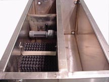
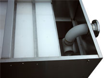
Separation Chamber
The oil separation chamber shall contain HD Q-PAC
Coalescing Media containing a minimum of 132 square
feet per cubic foot of effective coalescing surface
area. The medias needle like elements (plates)
shall be at 90 degrees to the horizontal or longitudinal
axis of the separator. Spacing between these elements
shall be spaced 3/16" apart for the removal
of a minimum of 99.9% of free droplets 40 micron
in size or greater. The elements are positioned
to create an angle of repose of 90 degrees to
facilitate the removal of solids that may tend
to build up on the coalescing surfaces, which
would increase velocities to the point of discharging
an unacceptable design flow rate shall be maintained
throughout the separator packed bed including
entrance and exit so as to prevent re-entrainment
of oils with water. Flow through the polypropylene
coalescing media shall be crossflow perpendicular
to the vertical media elements such that all 132
square feet/cubic foot of coalescing media surfaces
shall be pointing upwards so as not to be available
for contact with the crossflowing oily water.
The media shall have a minimum void of 87% void
volume to facilitate sludge and dirt particles
as they fall off the vertical elements and settle
in the sludge compartment. The media when installed
in crossflow OWS shall meet US EPA Method 413.2
and also European Standard 858-1 for oil water
separators.
Baffles
An oil retention & underflow weir, and overflow
weir. Position underflow weir to prevent re-suspension
of settled solids.
Sludge Chamber
The sludge chamber shall be located prior to the
coalescing compartment for the settling of any
solids. It shall also prevent any solids from
entering the clean water chamber. (Larger amounts
of solids can be collected in a sludge hopper
as an option.)
Oil Skimmer
The oil separation chamber will be provided with
a rotatable pipe skimmer for gravity decanting
of the separated oil to an integral product storage
tank or an external product storage tank.
Clean Water Chamber
The tank will be provided with a clean water chamber
which allows the water to leave the separator
by pumped / gravity flow through the clean water
outlet port.
Vents
1" vents will be provided with vent piping
to atmosphere.