 |
 Applications Applications |
 Automotive Automotive |
| Biodiesel |
| Dairy Industry |
| Industrial Wastewater |
| Food Processing Industry |
| Iron Removal |
| Latex Removal |
| Metals Treatment |
| Mining Industry |
| Municipal Wastewater |
| Odor Control |
| Petrochemical Industry |
| Poultry Industry |
| Products |
| Activated Carbon |
| Bag Filtration |
| Biological Treatment |
| Chemicals (Specialty) |
| Clarifiers |
| Controls |
| Dissolved Air Flotation |
| Dewatering |
| Evaporators |
| Membrane Filtration |
| Microbial Bacteria |
| Oil/Water Separators |
| Ozone |
| Pressure Filtration |
| Screens |
| Separators/Strainers |
 Hydrocyclone Separator Hydrocyclone Separator |
| Self Cleaning Suction Filter |
| Preliminary Strainers |
| Automatic Jet-Disc Filter |
| Automatic Jet-Disc Skid Mounted |
| Cone Filters |
| Tanks |
|
| the V-Series self-cleaning filters are designed to filter particuate with a limited amount of maintenanc or operation. The Reverser Drive mechanism is a simple design that allows these unique filters to contain fewer moving parts with easy to use controls. |
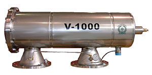
V-Series
Filters
The V-Series design is the most recent, state-of-the-art
self-cleaning screen filtration technology available
today. The complexity and cleaning efficiency of
any self-cleaning screen filter is in the mechanical
system that drives the cleaning process. The new
V-Series patented "Reverser Drive"
mechanism is the simplest and most efficient in
design resulting in:
- fewer moving parts (no limit switches or
pistons reversing the cleaning mechanism),
- simpler controls,
- reduced flush flow,
- greater cleaning efficiency, and
- lower maintenance requirements.
The V-Series’ 5 to 30 second flush cycle
is automatically initiated when a pressure differential
across the screen increases to 7 psi. The filter
remains on line, and the filtration process remains
uninterrupted during the cleaning process. And
the flush discharge is the lowest in the industry
resulting in minimal waste.
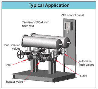
Every filtration project has unique
requirements, so the V-Series filters are constructed
to ASME code and are designed to incorporate a
broad range of construction material, pressure
and temperature options. Ecologix will custom
manufacture filters and skids that simplify installation
and meet specific requirements. Mesh / Micron Data |
V-1000 Schematices.PDF / V-1500 Schematics.PDF |
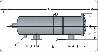 |
| Model |
Dimensions
- inches |
Screen
Area |
Nominal
Flow
GPM |
Flush
Flow |
#
of
Nozzles |
| A |
B |
C |
D |
E |
F |
G |
H |
J |
k |
L |
in/cubed |
| Length |
Body
Dia. |
Flush
Line |
|
|
|
|
|
Flange |
Clearance |
Clearance |
100µ |
200µ |
300µ |
Gallons |
| V-250 |
38.2 |
10.1 |
1
NPT |
7.1 |
11.5 |
9.4 |
9.2 |
13.5 |
2-3-4 |
30.0 |
12.0 |
224 |
270 |
360 |
400 |
8 |
2 |
| V-500 |
48.3 |
10.1 |
1
NPT |
7.7 |
21.5 |
9.0 |
9.1 |
13.5 |
3-4-6 |
40.0 |
12.0 |
448 |
540 |
720 |
800 |
15 |
4 |
| V-1000 |
60.6 |
15.2 |
2
NPT |
12.5 |
24.0 |
10.5 |
13.4 |
18.8 |
4-6-8 |
56.0 |
12.0 |
867 |
1040 |
1400 |
1520 |
15 |
4 |
| V-1500 |
72.6 |
15.2 |
2
NPT |
12.5 |
36.0 |
16.4 |
18.1 |
29.0 |
6-8-10 |
72.0 |
12.0 |
1300 |
1560 |
2080 |
2280 |
23 |
6 |
| V-2000 |
80.7 |
22.1 |
3
flange |
17.0 |
36.0 |
16.4 |
18.1 |
29.0 |
10-12-14 |
72.0 |
12.0 |
1696 |
2040 |
2720 |
3060 |
33 |
6 |
| V-2500 |
90.0 |
22.1 |
3
flange |
17.0 |
48.0 |
16.4 |
18.1 |
29.0 |
12-14-16 |
80.0 |
12.0 |
2262 |
2710 |
3840 |
4200 |
44 |
8 |
| V-3500 |
118.3 |
24.0 |
3
flange |
34.8 |
50.0 |
16.6 |
20.0 |
31.3 |
14-16-20 |
90.0 |
12.0 |
3060 |
3670 |
4900 |
5360 |
44 |
8 |
| V
Series Specifications |
| Materials |
|
| Filter
Body |
-
2" - 10" inlet/outlet, 316 SS
-10" - 20" inlet/outlet, epoxy coated carbon steel** |
| Screens |
-316L
SS sintered** |
| Flanges |
-AWWA
Class D** |
| Seals |
-
nitrile, viton, silicone |
| Filtraton
Range |
-15
to 1500 micron** |
| Flow
Range |
-35
to 3,670 gpm per filter (with 130 micron screen) |
| Max
Pressure |
-
150 psi (14.2 kg/cm sq.) |
| Min.
Pressure |
-35
psi (2.5 kg/cm sq.) |
| Max
Temp. |
-
176° F (80° C) |
| Flush
Cycle |
-
5 to 30 seconds |
| Control
Options |
-
VF 1B - battery powered, single filter
-VF - AC - electronic, up to 12 filters
-New - fully programmable, electronic, multiple
interface options |
| |
-**
Other options are available |
|
 |
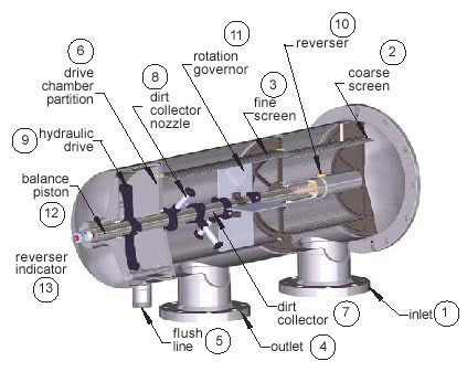 |
How
the V-Series Self-Cleaning Filters operate:
Dirty water enters the filter through the inlet (1) and then
passes through the coarse screen (2) from the outside in. It
flows from the inside of the coarse screen to the inside of the fine screen and
then passes through the fine screen (3) from the inside out.
Dirt is collected on the inside surface of the fine screen. The clean filtered
water then exits through the filter outlet (4) and on to the
system. As the dirt or cake builds up on the inside surface of the fine screen,
the pressure drop across the screen increases. When the pressure drop, (the DP
or differential pressure) reaches a preset level (7 psi), the filter controller
starts a flush cycle by opening a flush valve on the flush line (5).
This flush valve exhausts the drive chamber to atmosphere at “0” psi.
The flush line (5) is connected to the drive chamber which is
separated from the filtration chamber by a drive chamber partition (6).
However, the dirt collector (7) (a hollow pipe with dirt collector
nozzles) extends through the partition (6), thus providing a “path” from
the dirt collector nozzles (8) through the hydraulic drive (9),
into the drive chamber and out the flush line (5) to atmosphere.
The pressure around the dirt collector nozzle (8) is the pressure
inside the filter and as water flows through the “path”, it drops
to “0” psi when it leaves the flush line (5).
This creates an aggressive “suction” at the dirt collector nozzle
(8) opening. The dirt collector nozzle (8)
clearance at the fine screen (3) is very small. So, the extreme
low pressure at the nozzle opening creates a backflow which “sucks” the
dirt from the fine screen (3). |
The
hydraulic drive (9) has jets
on opposite sides near it’s ends. Water
jetting out of these openings (coming from the
dirt collector nozzles (8) creates
a reaction force (like a pin wheel) which rotates
the drive (9) and the dirt collector (7). As
the dirt collector (7) rotates, each dirt collector
nozzle (8) cleans a band on the fine screen (3).
As the dirt collector (7) rotates, the reverser
(10) (works like the level winder on your fishing
reel) causes the hydraulic drive (9) / dirt collector
(7) / dirt collector nozzle (8)
assembly to move back and forth.
The rotation
governor (11) helps control the rotation speed
of the dirt collector (7) assembly. The balance
piston (12) helps balance the transverse pressure
on the assembly, and powers the reverser indicator
(13) which provides visual indication of the dirt
collector (7) assembly movement showing that the
entire cleaning system is operating properly during
the rinse cycle.
After a preset time, the flush valve closes
and the rinse cycle is complete. Very little
rinse water is used for each rinse. Please note
the filter continues to supply water to the system
during the rinse cycle. |
|
|
326-2020/(678)514-2100")